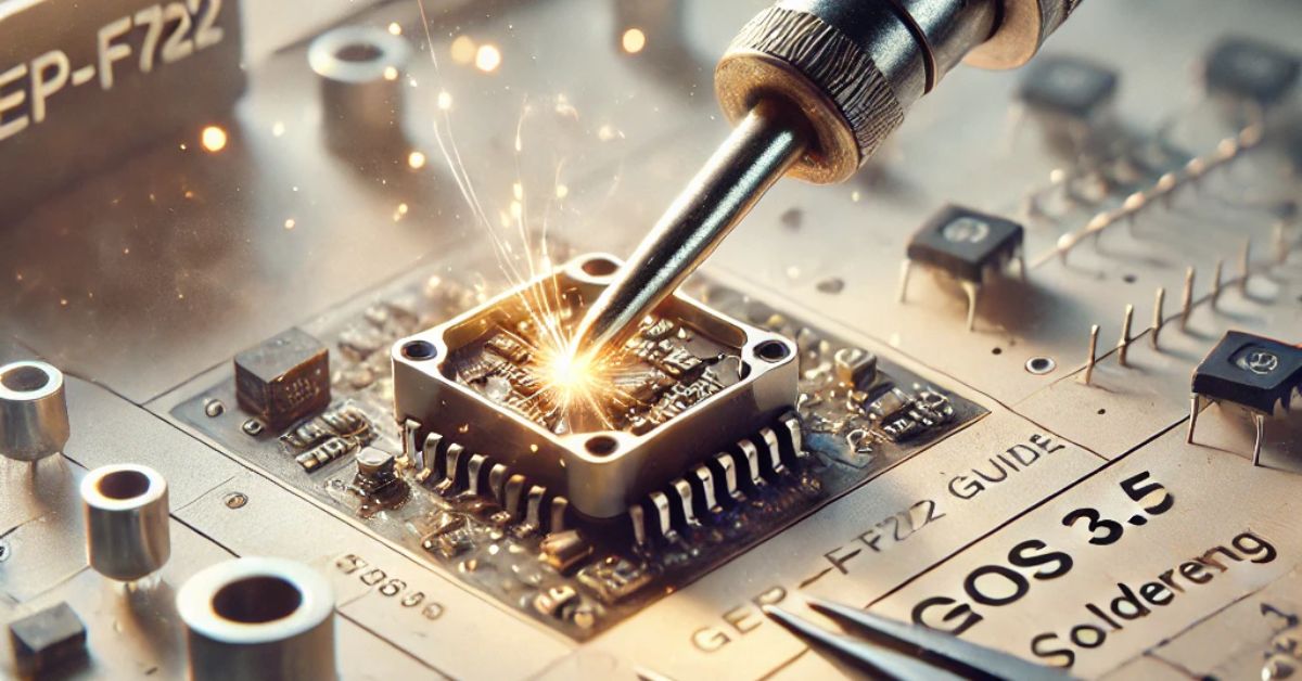
In the world of drone building and FPV (First-Person View) technology, soldering plays a pivotal role in ensuring the reliability and performance of your build. Among the popular flight controllers used by enthusiasts, the GEP-F722 stands out as a robust and versatile option, particularly when paired with the advanced capabilities of the AOS 3.5 frame. In this guide, we will delve into the aos 3.5 gep-f722 soldering intricacies of soldering components to the GEP-F722 flight controller, offering a detailed walkthrough, best practices, and troubleshooting tips.
Understanding the GEP-F722 Flight Controller
The GEP-F722 is a high-performance flight controller designed for advanced drone builds. Its F7 processor ensures powerful computational capabilities, making it suitable for running resource-intensive firmware like Betaflight, INAV, or EmuFlight. Key features include:
- Multiple UART Ports: Supports a variety of peripherals like GPS, Crossfire, and telemetry.
- Integrated OSD (On-Screen Display): Displays vital flight information on your FPV feed.
- BLHeli32 ESC Compatibility: Provides seamless communication with advanced electronic speed controllers.
- Current Sensing and Voltage Monitoring: Ensures accurate power management.
Tools and Materials Needed for Soldering
Before you begin soldering, ensure you have the following tools and materials:
- Soldering Iron: A high-quality soldering iron with adjustable temperature settings.
- Solder: Leaded solder (60/40 tin-lead ratio) is recommended for ease of use.
- Flux: A liquid or paste flux to enhance solder flow and adhesion.
- Solder Wick: For correcting mistakes and desoldering.
- Multimeter: Essential for continuity testing and verifying connections.
- Helping Hands or PCB Holder: Stabilizes the flight controller during soldering.
- Tweezers: Precision tools for handling small components.
- Heat Shrink Tubing: For insulating exposed wires and connections.
- Wire Stripper: Prepares wires for soldering.
Preparing for Soldering
1. Inspect the GEP-F722 Flight Controller
Before soldering, visually inspect the flight controller for any physical damage or manufacturing defects. Check for:
- Bent pins or connectors.
- Disconnected or poorly soldered components.
- Residual debris or contaminants on the board.
2. Plan Your Wiring Layout
Map out the connections you need for your build. Common peripherals include:
- ESC Connections: Motor outputs, battery voltage (VBAT), and ground.
- Receiver (RX): SBUS or Crossfire inputs.
- FPV Camera and VTX: Video input/output, power, and ground.
- Optional Sensors: GPS, barometer, or current sensor.
3. Tin Pads and Wires
Tinning involves applying a small amount of solder to both the soldering pads on the flight controller and the stripped ends of wires. This step improves adhesion and ensures a solid connection during soldering.
Tinning Process:
- Heat the soldering pad or wire end with the soldering iron.
- Apply a small amount of solder to the heated area.
- Remove the soldering iron once the solder flows smoothly.
Soldering Key Components
1. Electronic Speed Controllers (ESCs)
ESCs are critical for controlling motor speeds. Connect them to the flight controller using the following steps:
- Signal Wires: Solder the signal wires from the ESCs to the corresponding motor outputs on the flight controller.
- Power Wires: Connect the ESC’s VBAT and ground wires to the flight controller’s power pads.
- Telemetry (Optional): If your ESC supports telemetry, solder the telemetry wire to the designated UART pad.
2. Receiver (RX)
The receiver transmits signals from your transmitter to the flight controller. The connection depends on your receiver type (e.g., SBUS, Crossfire, or DSMX):
- Power: Solder the 5V and ground wires to the flight controller.
- Signal: Connect the signal wire to the appropriate UART RX pad.
- Telemetry (Optional): Some receivers provide telemetry feedback via a UART TX pad.
3. FPV Camera and Video Transmitter (VTX)
To transmit and display live video, connect the FPV camera and VTX:
- Camera: Solder the video signal wire to the “CAM” pad on the flight controller. Connect the power and ground wires to the appropriate pads.
- VTX: Attach the VTX video input to the “VOUT” pad. Connect power and ground wires to the specified pads. If your VTX supports SmartAudio or Tramp, solder the control wire to a UART TX pad.
4. Battery Leads
Connect the main battery leads to the flight controller’s VBAT and ground pads. Ensure these connections are secure, as they aos 3.5 gep-f722 soldering handle high current loads.
5. Peripherals
For optional peripherals like GPS or buzzers, solder their wires to the designated pads. GPS typically connects to a UART, while buzzers use dedicated pads marked “BZ+” and “BZ-”.
Best Practices for Soldering
1. Set the Correct Temperature
Maintain a soldering iron temperature between 350°C and 400°C. This range ensures efficient soldering without damaging components.
2. Use Flux Sparingly
Apply a small amount of flux to solder pads and wires to improve solder flow and adhesion. Avoid excessive use, as it can leave residue on the board.
3. Minimize Heat Exposure
Avoid prolonged contact between the soldering iron and components to prevent heat damage. Hold the iron on the pad just long enough for the solder to flow.
4. Ensure Proper Joint Formation
A good solder joint should appear shiny and smooth. Cold joints (dull or grainy) are weak and prone to failure.
5. Test Continuity
After soldering, use a multimeter to test the continuity of your connections. Verify that there are no unintended shorts between adjacent pads or traces.
Troubleshooting Common Issues
1. Cold Solder Joints
Symptoms: Poor electrical connection or intermittent functionality.
Solution: Reheat the joint and apply a small amount of fresh solder. Ensure proper heating and use flux if necessary.
2. Bridged Connections
Symptoms: Adjacent solder pads are connected unintentionally.
Solution: Use a solder wick or desoldering pump to remove excess solder. Recheck the connections for continuity.
3. Damaged Pads
Symptoms: Solder pads lift off the PCB due to excessive heat or force.
Solution: Use an alternate pad or trace, if available. For critical connections, consider repairing the pad with aos 3.5 gep-f722 soldering conductive epoxy.
4. Signal Noise or Interference
Symptoms: Erratic behavior or poor performance of peripherals.
Solution: Verify proper grounding and ensure signal wires are not running parallel to high-current power wires. Use shielded cables or ferrite rings if necessary.
Post-Soldering Tips
1. Inspect Your Work
Visually inspect all solder joints for quality. Ensure there are no bridges, cold joints, or exposed wires.
2. Clean the Board
Remove flux residue using isopropyl alcohol and a soft brush. This step prevents corrosion and improves electrical reliability.
3. Secure Wires
Use zip ties or adhesive mounts to secure wires and reduce stress on solder joints. Apply heat shrink tubing to exposed connections for insulation.
4. Test Functionality
Power up the flight controller and test all connected components. Verify motor rotation, receiver input, and FPV video output.
Conclusion
Soldering the GEP-F722 flight controller in an AOS 3.5 drone build is a rewarding process that requires patience, precision, and attention to detail. By following the steps outlined in this guide and adhering to best practices, you can achieve a robust and reliable build capable of delivering exceptional performance. Remember, practice is key—each solder joint brings you closer to mastering this essential skill.
FAQs
1. What is the ideal soldering temperature for the GEP-F722 flight controller?
The ideal soldering temperature ranges between 350°C and 400°C. This ensures efficient soldering without damaging the board.
2. How can I prevent solder bridges between adjacent pads?
To prevent solder bridges, use a fine-tipped soldering iron, apply minimal solder, and avoid excessive heat. If a bridge occurs, use a solder wick to remove excess solder.
3. What type of solder should I use for the GEP-F722?
Leaded solder with a 60/40 tin-lead ratio is recommended for its ease of use and reliable joints. Ensure you work in a well-ventilated area due to fumes.
4. Why is my flight controller not powering on after soldering?
Check for solder bridges, cold joints, or damaged pads. Verify continuity with a multimeter and ensure the battery leads are properly connected.
5. Can I repair a damaged solder pad on the GEP-F722?
Yes, you can repair a damaged pad by using an alternate pad or trace, or by applying conductive epoxy. Exercise caution to avoid further damage.
6. What precautions should I take when soldering sensitive components?
Minimize heat exposure by soldering quickly and efficiently. Use flux to improve solder flow and ensure a clean work environment to avoid contamination.


